

Login Form
Registration
Profile Informations
Login Datas
or login
Search results for 'Ther'
-
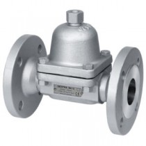
Thermostratic steam trap - BK15 - DN50 / PN40
Thermostatic steam trapLearn More -

Thermostratic steam trap - BK15 - DN40 / PN40
Thermostatic steam trapLearn More -
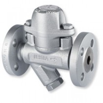
Thermostratic steam trap - BK46 - DN25 / PN40
"Thermostatic steam trap (max. ΔP 22 Bar)"Learn More -
Thermostratic steam trap - BK46 - DN20 / PN40
"Thermostatic steam trap (max. ΔP 22 Bar)"Learn More -
Thermostratic steam trap - BK46 - DN15 / PN40
"Thermostatic steam trap (max. ΔP 22 Bar)"Learn More -
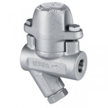
Thermostratic steam trap - BK45 - Threaded connection / DN25 / PN40
"Thermostatic steam trap (max. ΔP 22 Bar)"Learn More -

Thermostratic steam trap - BK45 - Threaded connection / DN20 / PN40
"Thermostatic steam trap (max. ΔP 22 Bar)"Learn More -

Thermostatic steam trap - BK45 - Threaded connection / DN15 / PN40
"Thermostatic steam trap (max. ΔP 22 Bar)"Learn More -

Thermostratic steam trap - BK45 -Flange connection / DN25 / PN40
"Thermostatic steam trap (max. ΔP 32 Bar)"Learn More -

Thermostratic steam trap - BK45 - Flange connection / DN20 / PN40
"Thermostatic steam trap (max. ΔP 32 Bar)"Learn More -

Thermostatic steam trap - BK45 - Flange connection / DN15 / PN40
"Thermostatic steam trap (max. ΔP 32 Bar)"Learn More -

Wafer type check valve Econ - Fig. 2634 - DN 100 / PN 40
Learn MoreEcon® (chromium) steel wafer type disc check valves with spring-loaded disc, metal seated, stainless steel trim, pressure rating PN 40, standard suitable for mounting between flanges acc. to DIN PN 6-40, short Face To Face, low weight and low pressure loss. Suitable for horizontal and vertical installation.
Application
Cold and hot water, oil, air, gases and other neutral media. Disc type check valves can also be used as vacuum breaker. -
Wafer type check valve Econ - Fig. 2634 - DN 80 / PN 40
Learn MoreEcon® (chromium) steel wafer type disc check valves with spring-loaded disc, metal seated, stainless steel trim, pressure rating PN 40, standard suitable for mounting between flanges acc. to DIN PN 6-40, short Face To Face, low weight and low pressure loss. Suitable for horizontal and vertical installation.
Application
Cold and hot water, oil, air, gases and other neutral media. Disc type check valves can also be used as vacuum breaker. -
Wafer type check valve Econ - Fig. 2634 - DN 65 / PN 40
Learn MoreEcon® (chromium) steel wafer type disc check valves with spring-loaded disc, metal seated, stainless steel trim, pressure rating PN 40, standard suitable for mounting between flanges acc. to DIN PN 6-40, short Face To Face, low weight and low pressure loss. Suitable for horizontal and vertical installation.
Application
Cold and hot water, oil, air, gases and other neutral media. Disc type check valves can also be used as vacuum breaker. -
Wafer type check valve Econ - Fig. 2634 - DN 50 / PN 40
Learn MoreEcon® (chromium) steel wafer type disc check valves with spring-loaded disc, metal seated, stainless steel trim, pressure rating PN 40, standard suitable for mounting between flanges acc. to DIN PN 6-40, short Face To Face, low weight and low pressure loss. Suitable for horizontal and vertical installation.
Application
Cold and hot water, oil, air, gases and other neutral media. Disc type check valves can also be used as vacuum breaker. -
Wafer type check valve Econ - Fig. 2634 - DN 40 / PN 40
Learn MoreEcon® (chromium) steel wafer type disc check valves with spring-loaded disc, metal seated, stainless steel trim, pressure rating PN 40, standard suitable for mounting between flanges acc. to DIN PN 6-40, short Face To Face, low weight and low pressure loss. Suitable for horizontal and vertical installation.
Application
Cold and hot water, oil, air, gases and other neutral media. Disc type check valves can also be used as vacuum breaker. -
Wafer type check valve Econ - Fig. 2634 - DN 32 / PN 40
Learn MoreEcon® (chromium) steel wafer type disc check valves with spring-loaded disc, metal seated, stainless steel trim, pressure rating PN 40, standard suitable for mounting between flanges acc. to DIN PN 6-40, short Face To Face, low weight and low pressure loss. Suitable for horizontal and vertical installation.
Application
Cold and hot water, oil, air, gases and other neutral media. Disc type check valves can also be used as vacuum breaker. -
Wafer type check valve Econ - Fig. 2634 - DN 25 / PN 40
Learn MoreEcon® (chromium) steel wafer type disc check valves with spring-loaded disc, metal seated, stainless steel trim, pressure rating PN 40, standard suitable for mounting between flanges acc. to DIN PN 6-40, short Face To Face, low weight and low pressure loss. Suitable for horizontal and vertical installation.
Application
Cold and hot water, oil, air, gases and other neutral media. Disc type check valves can also be used as vacuum breaker. -
Wafer type check valve Econ - Fig. 2634 - DN 20 / PN 40
Learn MoreEcon® (chromium) steel wafer type disc check valves with spring-loaded disc, metal seated, stainless steel trim, pressure rating PN 40, standard suitable for mounting between flanges acc. to DIN PN 6-40, short Face To Face, low weight and low pressure loss. Suitable for horizontal and vertical installation.
Application
Cold and hot water, oil, air, gases and other neutral media. Disc type check valves can also be used as vacuum breaker. -
Wafer type check valve Econ - Fig. 2634 - DN 15 / PN 40
Learn MoreEcon® (chromium) steel wafer type disc check valves with spring-loaded disc, metal seated, stainless steel trim, pressure rating PN 40, standard suitable for mounting between flanges acc. to DIN PN 6-40, short Face To Face, low weight and low pressure loss. Suitable for horizontal and vertical installation.
Application
Cold and hot water, oil, air, gases and other neutral media. Disc type check valves can also be used as vacuum breaker. -

Globe valve ARI 35.046 Plug with marginal seat - Fig. 153 - DN 200 / PN 40
Cast steel Econ® bellow sealed globe valves, SS trim, pressure rating PN25/40, straight pattern, flanged ends acc. to DIN PN 25/40, outside screwed stem and non-rising handwheel.Learn More -
Globe valve ARI 35.046 Plug with marginal seat - Fig. 153 - DN 250 / PN 25
Cast steel Econ® bellow sealed globe valves, SS trim, pressure rating PN25/40, straight pattern, flanged ends acc. to DIN PN 25/40, outside screwed stem and non-rising handwheel.Learn More -
Globe valve ARI 35.046 Plug with marginal seat - Fig. 153 - DN 200 / PN 25
Cast steel Econ® bellow sealed globe valves, SS trim, pressure rating PN25/40, straight pattern, flanged ends acc. to DIN PN 25/40, outside screwed stem and non-rising handwheel.Learn More -
Globe valve ARI 35.046 Plug with marginal seat - Fig. 153 - DN 150 / PN 40
Cast steel Econ® bellow sealed globe valves, SS trim, pressure rating PN25/40, straight pattern, flanged ends acc. to DIN PN 25/40, outside screwed stem and non-rising handwheel.Learn More -
Globe valve ARI 35.046 Plug with marginal seat - Fig. 153 - DN 125 / PN 40
Cast steel Econ® bellow sealed globe valves, SS trim, pressure rating PN25/40, straight pattern, flanged ends acc. to DIN PN 25/40, outside screwed stem and non-rising handwheel.Learn More -
Globe valve ARI 35.046 Plug with marginal seat - Fig. 153 - DN 100 / PN 40
Cast steel Econ® bellow sealed globe valves, SS trim, pressure rating PN25/40, straight pattern, flanged ends acc. to DIN PN 25/40, outside screwed stem and non-rising handwheel.Learn More -
Globe valve ARI 35.046 Plug with marginal seat - Fig. 153 - DN 80 / PN 40
Cast steel Econ® bellow sealed globe valves, SS trim, pressure rating PN25/40, straight pattern, flanged ends acc. to DIN PN 25/40, outside screwed stem and non-rising handwheel.Learn More -
Globe valve ARI 35.046 Plug with marginal seat - Fig. 153 - DN 65 / PN 40
Cast steel Econ® bellow sealed globe valves, SS trim, pressure rating PN25/40, straight pattern, flanged ends acc. to DIN PN 25/40, outside screwed stem and non-rising handwheel.Learn More -
Globe valve ARI 35.046 Plug with marginal seat- Fig. 153 - DN 50 / PN 40
Cast steel Econ® bellow sealed globe valves, SS trim, pressure rating PN25/40, straight pattern, flanged ends acc. to DIN PN 25/40, outside screwed stem and non-rising handwheel.Learn More -
Globe valve ARI 35.046 Plug with marginal seat - Fig. 153 - DN 40 / PN 40
Cast steel Econ® bellow sealed globe valves, SS trim, pressure rating PN25/40, straight pattern, flanged ends acc. to DIN PN 25/40, outside screwed stem and non-rising handwheel.Learn More -
Globe valve ARI 35.046 Plug with marginal seat - Fig. 153 - DN 32 / PN 40
Cast steel Econ® bellow sealed globe valves, SS trim, pressure rating PN25/40, straight pattern, flanged ends acc. to DIN PN 25/40, outside screwed stem and non-rising handwheel.Learn More -
Globe valve ARI 35.046 Plug with marginal seat - Fig. 153 - DN 25 / PN 40
Cast steel Econ® bellow sealed globe valves, SS trim, pressure rating PN25/40, straight pattern, flanged ends acc. to DIN PN 25/40, outside screwed stem and non-rising handwheel.Learn More -
Globe valve ARI 35.046 Plug with marginal seat - Fig. 153 - DN 20 / PN 40
Cast steel Econ® bellow sealed globe valves, SS trim, pressure rating PN25/40, straight pattern, flanged ends acc. to DIN PN 25/40, outside screwed stem and non-rising handwheel.Learn More -
Globe valve ARI 35.046 Plug with marginal seat - Fig. 153 - DN 15 / PN 40
Cast steel Econ® bellow sealed globe valves, SS trim, pressure rating PN25/40, straight pattern, flanged ends acc. to DIN PN 25/40, outside screwed stem and non-rising handwheel.Learn More -

Globe valve fixed disc - Fig. 247 - DN 150 / PN 16
Econ® ductile cast iron globe valves with stainless steel trim, pressure rating PN 16, straight pattern, flanged ends acc. to DIN PN 10/16, outside screw & yoke and rising handwheel.Learn More -
Globe valve fixed disc - Fig. 247 - DN 125 / PN 16
Econ® ductile cast iron globe valves with stainless steel trim, pressure rating PN 16, straight pattern, flanged ends acc. to DIN PN 10/16, outside screw & yoke and rising handwheel.Learn More -
Globe valve fixed disc - Fig. 247 - DN 100 / PN 16
Econ® ductile cast iron globe valves with stainless steel trim, pressure rating PN 16, straight pattern, flanged ends acc. to DIN PN 10/16, outside screw & yoke and rising handwheel.Learn More -
Globe valve fixed disc - Fig. 247 - DN 80 / PN 16
Econ® ductile cast iron globe valves with stainless steel trim, pressure rating PN 16, straight pattern, flanged ends acc. to DIN PN 10/16, outside screw & yoke and rising handwheel.Learn More -
Globe valve fixed disc - Fig. 247 - DN 65 / PN 16
Econ® ductile cast iron globe valves with stainless steel trim, pressure rating PN 16, straight pattern, flanged ends acc. to DIN PN 10/16, outside screw & yoke and rising handwheel.Learn More -
Globe valve fixed disc - Fig. 247 - DN 50 / PN 16
Econ® ductile cast iron globe valves with stainless steel trim, pressure rating PN 16, straight pattern, flanged ends acc. to DIN PN 10/16, outside screw & yoke and rising handwheel.Learn More -
Globe valve fixed disc - Fig. 247 - DN 40 / PN 16
Econ® ductile cast iron globe valves with stainless steel trim, pressure rating PN 16, straight pattern, flanged ends acc. to DIN PN 10/16, outside screw & yoke and rising handwheel.Learn More -
Globe valve fixed disc - Fig. 247 - DN 32 / PN 16
Econ® ductile cast iron globe valves with stainless steel trim, pressure rating PN 16, straight pattern, flanged ends acc. to DIN PN 10/16, outside screw & yoke and rising handwheel.Learn More -
Globe valve fixed disc - Fig. 247 - DN 25 / PN 16
Econ® ductile cast iron globe valves with stainless steel trim, pressure rating PN 16, straight pattern, flanged ends acc. to DIN PN 10/16, outside screw & yoke and rising handwheel.Learn More -
Globe valve fixed disc - Fig. 247 - DN 20 / PN 16
Econ® ductile cast iron globe valves with stainless steel trim, pressure rating PN 16, straight pattern, flanged ends acc. to DIN PN 10/16, outside screw & yoke and rising handwheel.Learn More -
Globe valve fixed disc - Fig. 247 - DN 15 / PN 16
Econ® ductile cast iron globe valves with stainless steel trim, pressure rating PN 16, straight pattern, flanged ends acc. to DIN PN 10/16, outside screw & yoke and rising handwheel.Learn More -

Globe valve fixed disc - Fig. 417 - DN 200 / PN 40
Econ® cast steel globe valves with stainless steel trim, pressure rating PN 16 - 40, straight pattern, flanged ends acc. to DIN PN16/40, outside screw & yoke and rising handwheel.Learn More -
Globe valve fixed disc - Fig. 417 - DN 150 / PN 40
Econ® cast steel globe valves with stainless steel trim, pressure rating PN 16 - 40, straight pattern, flanged ends acc. to DIN PN16/40, outside screw & yoke and rising handwheel.Learn More -
Globe valve fixed disc - Fig. 417 - DN 125 / PN 40
Econ® cast steel globe valves with stainless steel trim, pressure rating PN 16 - 40, straight pattern, flanged ends acc. to DIN PN16/40, outside screw & yoke and rising handwheel.Learn More -
Globe valve fixed disc - Fig. 417 - DN 100 / PN 40
Econ® cast steel globe valves with stainless steel trim, pressure rating PN 16 - 40, straight pattern, flanged ends acc. to DIN PN16/40, outside screw & yoke and rising handwheel.Learn More -
Globe valve fixed disc - Fig. 417 - DN 80 / PN 40
Econ® cast steel globe valves with stainless steel trim, pressure rating PN 16 - 40, straight pattern, flanged ends acc. to DIN PN16/40, outside screw & yoke and rising handwheel.Learn More -
Globe valve fixed disc - Fig. 417 - DN 65 / PN 40
Econ® cast steel globe valves with stainless steel trim, pressure rating PN 16 - 40, straight pattern, flanged ends acc. to DIN PN16/40, outside screw & yoke and rising handwheel.Learn More -
Globe valve fixed disc - Fig. 417 - DN 50 / PN 40
Econ® cast steel globe valves with stainless steel trim, pressure rating PN 16 - 40, straight pattern, flanged ends acc. to DIN PN16/40, outside screw & yoke and rising handwheel.Learn More -
Globe valve fixed disc - Fig. 417 - DN 40 / PN 40
Econ® cast steel globe valves with stainless steel trim, pressure rating PN 16 - 40, straight pattern, flanged ends acc. to DIN PN16/40, outside screw & yoke and rising handwheel.Learn More -
Globe valve fixed disc - Fig. 417 - DN 32 / PN 40
Econ® cast steel globe valves with stainless steel trim, pressure rating PN 16 - 40, straight pattern, flanged ends acc. to DIN PN16/40, outside screw & yoke and rising handwheel.Learn More -
Globe valve fixed disc - Fig. 417 - DN 25 / PN 40
Econ® cast steel globe valves with stainless steel trim, pressure rating PN 16 - 40, straight pattern, flanged ends acc. to DIN PN16/40, outside screw & yoke and rising handwheel.Learn More -
Globe valve fixed disc - Fig. 417 - DN 20 / PN 40
Econ® cast steel globe valves with stainless steel trim, pressure rating PN 16 - 40, straight pattern, flanged ends acc. to DIN PN16/40, outside screw & yoke and rising handwheel.Learn More -
Globe valve fixed disc - Fig. 417 - DN 15 / PN 40
Econ® cast steel globe valves with stainless steel trim, pressure rating PN 16 - 40, straight pattern, flanged ends acc. to DIN PN16/40, outside screw & yoke and rising handwheel.Learn More -

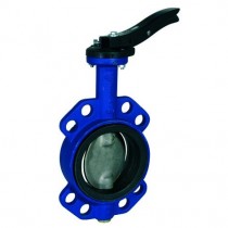
Butterfly valve Econ - Fig. 6331 - DN 150 / PN 16 / EPDM
Econ® ductile cast iron butterfly valve, semi-monoflange type with centric disc, split shafts and rubber lined body.Learn More -

Butterfly valve Econ - Fig. 6331 - DN 125 / PN 16 / EPDM
Econ® ductile cast iron butterfly valve, semi-monoflange type with centric disc, split shafts and rubber lined body.Learn More -

Butterfly valve Econ - Fig. 6331 - DN 100 / PN 16 / EPDM
Econ® ductile cast iron butterfly valve, semi-monoflange type with centric disc, split shafts and rubber lined body.Learn More -

Butterfly valve Econ - Fig. 6331 - DN 80 / PN 16 / EPDM
Econ® ductile cast iron butterfly valve, semi-monoflange type with centric disc, split shafts and rubber lined body.Learn More -

Butterfly valve Econ - Fig. 6331 - DN 65 / PN 16 / EPDM
Econ® ductile cast iron butterfly valve, semi-monoflange type with centric disc, split shafts and rubber lined body.Learn More -

Butterfly valve Econ - Fig. 6331 - DN 50 / PN 16 / EPDM
Econ® ductile cast iron butterfly valve, semi-monoflange type with centric disc, split shafts and rubber lined body.Learn More -

Butterfly valve Econ - Fig. 6331 - DN 40 / PN 16 / EPDM
Econ® ductile cast iron butterfly valve, semi-monoflange type with centric disc, split shafts and rubber lined body.Learn More -

Butterfly valve Econ - Fig. 6331 - DN 32 / PN 16 / EPDM
Econ® ductile cast iron butterfly valve, semi-monoflange type with centric disc, split shafts and rubber lined body.Learn More -

Butterfly valve Econ - Fig. 6331 - DN 25 /PN 16 / EPDM
Econ® ductile cast iron butterfly valve, semi-monoflange type with centric disc, split shafts and rubber lined body.Learn More -

Butterfly valve Econ - Fig. 6331 - DN 200 / PN 16 / NBR
Econ® ductile cast iron butterfly valve, semi-monoflange type with centric disc, split shafts and rubber lined body.Learn More -

Butterfly valve Econ - Fig. 6331 - DN 200 / PN 16 / EPDM
Econ® ductile cast iron butterfly valve, semi-monoflange type with centric disc, split shafts and rubber lined body.Learn More -

Butterfly valve Econ - Fig. 6331 - DN 150 / PN 16 / NBR
Econ® ductile cast iron butterfly valve, semi-monoflange type with centric disc, split shafts and rubber lined body.Learn More -

Butterfly valve Econ - Fig. 6331 - DN 125 / PN 16 / NBR
Econ® ductile cast iron butterfly valve, semi-monoflange type with centric disc, split shafts and rubber lined body.Learn More -
Butterfly valve Econ - Fig. 6331 - DN 100 / PN 16 / NBR
Econ® ductile cast iron butterfly valve, semi-monoflange type with centric disc, split shafts and rubber lined body.Learn More -

Butterfly valve Econ - Fig. 6331 - DN 80 / PN 16 / NBR
Econ® ductile cast iron butterfly valve, semi-monoflange type with centric disc, split shafts and rubber lined body.Learn More -

Butterfly valve Econ - Fig. 6331 - DN 65 / PN 16 / NBR
Econ® ductile cast iron butterfly valve, semi-monoflange type with centric disc, split shafts and rubber lined body.Learn More -

Butterfly valve Econ - Fig. 6331 - DN 50 / PN 16 / NBR
Econ® ductile cast iron butterfly valve, semi-monoflange type with centric disc, split shafts and rubber lined body.Learn More -

Butterfly valve Econ - Fig. 6331 - DN 40 / PN 16 / NBR
Econ® ductile cast iron butterfly valve, semi-monoflange type with centric disc, split shafts and rubber lined body.Learn More -

Butterfly valve Econ - Fig. 6331 - DN 32 / PN 16 / NBR
Econ® ductile cast iron butterfly valve, semi-monoflange type with centric disc, split shafts and rubber lined body.Learn More -

Butterfly valve Econ - Fig. 6331 - DN 25 / PN 16 / NBR
Econ® ductile cast iron butterfly valve, semi-monoflange type with centric disc, split shafts and rubber lined body.Learn More -

Pressure gauge siphon - Fig. 350 - 3/8" / PN 25
Seamless Steel siphon pipe with threaded connections.Learn More -
Pressure gauge siphon - Fig. 350 - 1/4" / PN 25
Seamless Steel siphon pipe with threaded connections.Learn More -
Pressure gauge siphon - Fig. 350 - 1/2" / PN 25
Seamless Steel siphon pipe with threaded connections.Learn More -

Bimetal thermometer Econ - Fig. 661 - 160 MM / 0 - 120 °C / Insert length 160 MM
Learn MoreEcon ® thermometers to EN Standard 13190, suitable for general and industrial environment. With removable brass thermowell secured by a locking screw.
-
Bimetal thermometer Econ - Fig. 661 - 160 MM / 0 - 120 °C / Insert length 100 MM
Learn MoreEcon ® thermometers to EN Standard 13190, suitable for general and industrial environment. With removable brass thermowell secured by a locking screw.
-
Bimetal thermometer Econ - Fig. 661 - 160 MM / 0 - 120 °C / Insert length 60 MM
Learn MoreEcon ® thermometers to EN Standard 13190, suitable for general and industrial environment. With removable brass thermowell secured by a locking screw.
-
Bimetal thermometer Econ - Fig. 661 - 100 MM / 0 - 200 °C / Insert length 160 MM
Learn MoreEcon ® thermometers to EN Standard 13190, suitable for general and industrial environment. With removable brass thermowell secured by a locking screw.
-
Bimetal thermometer Econ - Fig. 661 - 100 MM / 0 - 200 °C / Insert length 100 MM
Learn MoreEcon ® thermometers to EN Standard 13190, suitable for general and industrial environment. With removable brass thermowell secured by a locking screw.
-
Bimetal thermometer Econ - Fig. 661 - 100 MM / 0 - 200 °C / Insert length 60 MM
Learn MoreEcon ® thermometers to EN Standard 13190, suitable for general and industrial environment. With removable brass thermowell secured by a locking screw.
-
Bimetal thermometer Econ - Fig. 661 - 100 MM / 0 - 120 °C / Insert length 250 MM
Learn MoreEcon ® thermometers to EN Standard 13190, suitable for general and industrial environment. With removable brass thermowell secured by a locking screw.
-
Bimetal thermometer Econ - Fig. 661 - 100 MM / 0 - 120 °C / Insert length 160 MM
Learn MoreEcon ® thermometers to EN Standard 13190, suitable for general and industrial environment. With removable brass thermowell secured by a locking screw.
-
Bimetal thermometer Econ - Fig. 661 - 100 MM / 0 - 120 °C / Insert length 100 MM
Learn MoreEcon ® thermometers to EN Standard 13190, suitable for general and industrial environment. With removable brass thermowell secured by a locking screw.
-
Bimetal thermometer Econ - Fig. 661 - 100 MM / 0 - 120 °C / Insert length 60 MM
Learn MoreEcon ® thermometers to EN Standard 13190, suitable for general and industrial environment. With removable brass thermowell secured by a locking screw.
-
Bimetal thermometer Econ - Fig. 661 - 100 MM / 0 - 120 °C / Insert length 40 MM
Learn MoreEcon ® thermometers to EN Standard 13190, suitable for general and industrial environment. With removable brass thermowell secured by a locking screw.
-
Bimetal thermometer Econ - Fig. 661 - 100 MM / 0 - 60 °C / Insert length 100 MM
Learn MoreEcon ® thermometers to EN Standard 13190, suitable for general and industrial environment. With removable brass thermowell secured by a locking screw.
-
Bimetal thermometer Econ - Fig. 661 - 100 MM / 0 - 60 °C / Insert length 60 MM
Learn MoreEcon ® thermometers to EN Standard 13190, suitable for general and industrial environment. With removable brass thermowell secured by a locking screw.
-
Bimetal thermometer Econ - Fig. 661 - 100 MM / 0 - 60 °C / Insert length 40 MM
Learn MoreEcon ® thermometers to EN Standard 13190, suitable for general and industrial environment. With removable brass thermowell secured by a locking screw.
-
Bimetal thermometer Econ - Fig. 661 - 100 MM / -30 - 50 °C / Insert length 160 MM
Learn MoreEcon ® thermometers to EN Standard 13190, suitable for general and industrial environment. With removable brass thermowell secured by a locking screw.
-
Bimetal thermometer Econ - Fig. 661 - 100 MM / -30 - 50 °C / Insert length 100 MM
Learn MoreEcon ® thermometers to EN Standard 13190, suitable for general and industrial environment. With removable brass thermowell secured by a locking screw.
-
Bimetal thermometer Econ - Fig. 661 - 100 MM / -30 - 50 °C / Insert length 60 MM
Learn MoreEcon ® thermometers to EN Standard 13190, suitable for general and industrial environment. With removable brass thermowell secured by a locking screw.
-
Bimetal thermometer Econ - Fig. 661 - 100 MM / -30 - 50 °C / Insert length 40 MM
Learn MoreEcon ® thermometers to EN Standard 13190, suitable for general and industrial environment. With removable brass thermowell secured by a locking screw.
-
Bimetal thermometer Econ - Fig. 661 - 63 MM / 0 - 200 °C / Insert length 60 MM
Learn MoreEcon ® thermometers to EN Standard 13190, suitable for general and industrial environment. With removable brass thermowell secured by a locking screw.
-
Bimetal thermometer Econ - Fig. 661 - 63 MM / 0 - 200 °C / Insert length 40 MM
Learn MoreEcon ® thermometers to EN Standard 13190, suitable for general and industrial environment. With removable brass thermowell secured by a locking screw.
-
Bimetal thermometer Econ - Fig. 661 - 63 MM / 0 - 120 °C / Insert length 250 MM
Learn MoreEcon ® thermometers to EN Standard 13190, suitable for general and industrial environment. With removable brass thermowell secured by a locking screw.
-
Bimetal thermometer Econ - Fig. 661 - 63 MM / 0 - 120 °C / Insert length 160 MM
Learn MoreEcon ® thermometers to EN Standard 13190, suitable for general and industrial environment. With removable brass thermowell secured by a locking screw.
-
Bimetal thermometer Econ - Fig. 661 - 63 MM / 0 - 120 °C / Insert length 100 MM
Learn MoreEcon ® thermometers to EN Standard 13190, suitable for general and industrial environment. With removable brass thermowell secured by a locking screw.
-
Bimetal thermometer Econ - Fig. 661 - 63 MM / 0 - 120 °C / Insert length 60 MM
Learn MoreEcon ® thermometers to EN Standard 13190, suitable for general and industrial environment. With removable brass thermowell secured by a locking screw.
-
Bimetal thermometer Econ - Fig. 661 - 63 MM / 0 - 120 °C / Insert length 40 MM
Learn MoreEcon ® thermometers to EN Standard 13190, suitable for general and industrial environment. With removable brass thermowell secured by a locking screw.
-
Bimetal thermometer Econ - Fig. 661 - 63 MM / 0 - 60 °C / Insert length 100 MM
Learn MoreEcon ® thermometers to EN Standard 13190, suitable for general and industrial environment. With removable brass thermowell secured by a locking screw.
-
Bimetal thermometer Econ - Fig. 661 - 63 MM / 0 - 60 °C / Insert length 60 MM
Learn MoreEcon ® thermometers to EN Standard 13190, suitable for general and industrial environment. With removable brass thermowell secured by a locking screw.
-
Bimetal thermometer Econ - Fig. 661 - 63 MM / 0 - 60 °C / Insert length 40 MM
Learn MoreEcon ® thermometers to EN Standard 13190, suitable for general and industrial environment. With removable brass thermowell secured by a locking screw.
-
Bimetal thermometer Econ - Fig. 661 - 63 MM / -30 - 50 °C / Insert length 100 MM
Learn MoreEcon ® thermometers to EN Standard 13190, suitable for general and industrial environment. With removable brass thermowell secured by a locking screw.
-
Bimetal thermometer Econ - Fig. 661 - 63 MM / -30 - 50 °C / Insert length 60 MM
Learn MoreEcon ® thermometers to EN Standard 13190, suitable for general and industrial environment. With removable brass thermowell secured by a locking screw.
-
Bimetal thermometer Econ - Fig. 661 - 63 MM / -30 - 50 °C / Insert length 40 MM
Learn MoreEcon ® thermometers to EN Standard 13190, suitable for general and industrial environment. With removable brass thermowell secured by a locking screw.
-
Bimetal thermometer Econ - Fig. 661 - 80 MM / 0 - 200 °C / Insert length 60 MM
Learn MoreEcon ® thermometers to EN Standard 13190, suitable for general and industrial environment. With removable brass thermowell secured by a locking screw.
-
Bimetal thermometer Econ - Fig. 661 - 80 MM / 0 - 120 °C / Insert length 160 MM
Learn MoreEcon ® thermometers to EN Standard 13190, suitable for general and industrial environment. With removable brass thermowell secured by a locking screw.
-
Bimetal thermometer Econ - Fig. 661 - 80 MM / 0 - 120 °C / Insert length 100 MM
Learn MoreEcon ® thermometers to EN Standard 13190, suitable for general and industrial environment. With removable brass thermowell secured by a locking screw.
-
Bimetal thermometer Econ - Fig. 661 - 80 MM / 0 - 120 °C / Insert length 60 MM
Learn MoreEcon ® thermometers to EN Standard 13190, suitable for general and industrial environment. With removable brass thermowell secured by a locking screw.
-
Bimetal thermometer Econ - Fig. 661 - 80 MM / 0 - 120 °C / Insert length 40 MM
Learn MoreEcon ® thermometers to EN Standard 13190, suitable for general and industrial environment. With removable brass thermowell secured by a locking screw.
-
Bimetal thermometer Econ - Fig. 661 - 80 MM / -30 - 50 °C /Insert length 100 MM
Learn MoreEcon ® thermometers to EN Standard 13190, suitable for general and industrial environment. With removable brass thermowell secured by a locking screw.
-
Bimetal thermometer Econ - Fig. 661 - 80 MM / -30 - 50 °C / Insert length 60 MM
Learn MoreEcon ® thermometers to EN Standard 13190, suitable for general and industrial environment. With removable brass thermowell secured by a locking screw.
-
Bimetal thermometer Econ - Fig. 661 - 80 MM / -30 - 50 °C / Insert length 40 MM
Learn MoreEcon ® thermometers to EN Standard 13190, suitable for general and industrial environment. With removable brass thermowell secured by a locking screw.


